Drawing Lines is Hard
Twitter: @mattdesl
Drawing lines might not sound like rocket science, but it’s damn difficult to do well in OpenGL, particularly WebGL. Here I explore a few different techniques for 2D and 3D line rendering, and accompany each with a small canvas demo.
Source for demos can be found here:
https://github.com/mattdesl/webgl-lines
Line Primitives #
WebGL includes support for lines with gl.LINES, gl.LINE_STRIP, and gl.LINE_LOOP. Sounds great, right? Not really. Here are just a few issues with that:
- Drivers may implement the rendering/filtering slightly differently, and you may not get a consistent render across devices or browsers
- The maximum line width is driver-dependent. Users running ANGLE, for example, will get a maximum of 1.0, which is pretty useless. On my new Yosemite machine, line width maxes out at about 10.
- No control over line join or end cap styles
- MSAA is not supported in all devices, and most browsers do not support it for off-screen buffers. You may end up with jagged lines
- For dashed/dotted lines,
glLineStipplehas been deprecated and doesn’t exist in WebGL
In some demos, like the one above, gl.LINES might be acceptable, but in most cases it’s inadequate for production quality line rendering.
Triangulated Lines #
A common alternative is to break a line into triangles or triangle strips, and then render them as regular geometry. This gives you the most control over the line, allowing for end caps, specific joins, unions (for overlapping transparent areas), and so forth. This can also lead to some more creative and interesting line rendering, as in the above demo.
A typical way of achieving this is to get the normals for each point along a path, and expand outwards by half the thickness on either side. For an implementation, see polyline-normals. The math behind the miter join is discussed here.
More advanced meshes may need to emit new geometries for end caps, bevel joins, feathering, and so forth. Handling these edge cases can get fairly complex, as you can see in Vaser C/C++ source.
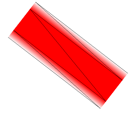
For anti-aliasing, you have a few options:
- hope that MSAA is supported and that you will never need the lines rendered to an off-screen buffer
- add more triangles for the feathered edges of a stroke (as in this image)
- use a texture lookup to gradate the alpha; very easy but does not scale well
- in the fragment shader, compute the anti-aliasing based on the projected scale of the stroke in screen space
- render prefiltered
gl.LINESas a second pass, around the edge of your stroke
Note: a drawback that comes with miter-joined lines is sharp edges. When the angle connecting two segments is very sharp, the miter length grows exponentially toward infinity, and causes huge artifacts in rendering. In some applications this may not be a problem, in others you might want to limit the miter or fall back to another join (i.e. bevel) when the angle is too sharp.
The above Triangles demo uses extrude-polyline, a small work-in-progress module for building a triangulated mesh out of a 2D polyline. Eventually it aims to support round joins/caps and proper miter limiting.
Expanding in a Vertex Shader #
Triangulation can add a fair amount of complexity to your code, and the mesh needs to be re-constructed when the stroke and join style changes. If you just want simple thick lines in WebGL, it can be a bit overkill.
This demo above expands the stroke in the vertex shader, where the thickness is a uniform. We submit two vertices for each point in our path, and pass the line normals and miter lengths as vertex attributes. Each pair has one normal (or miter) flipped, so that the two points are pushed away from the centre to form a thick line.
attribute vec2 position;
attribute vec2 normal;
attribute float miter;
uniform mat4 projection;

void main() {
    //push the point along its normal by half thickness
    vec2 p = position.xy + vec2(normal * thickness/2.0 * miter);
    gl_Position = projection * vec4(p, 0.0, 1.0);
}
The inner stroke effect on the left (click the canvas to animate it) is created in the fragment shader using the signed distance from centre. We can also achieve line dashes, gradients, glows, and other effects by passing distanceAlongPath as another vertex attribute.
? For a ThreeJS implementation of this approach, including line dashes, see three-line-2d.
Screen-Space Projected Lines #
The previous demo works well for 2D (orthographic) lines, but may not fit your design needs in 3D space. To give the line a constant thickness regardless of the 3D view, we need to expand the line after projecting it into screen space.
Like the last demo, we need to submit each point twice, with mirrored orientations so they are pushed away from each other. However, instead of computing the normal and miter length CPU-side, we do it in the vertex shader. To do this, we need to send along vertex attributes for the next and previous positions along the path.
In the vertex shader, we compute our join and extrusion in screen space to ensure the constant thickness. To work in screen space, we need to use the illusive homogeneous component, W. Also known as “perspective divide.” This gives us Normalized Device Coordinates (NDC), which lie in the range [-1, 1]. We then correct for aspect ratio before expanding our lines. We also do the same for previous and next positions along the path:
mat4 projViewModel = projection * view * model;

//into clip space
vec4 currentProjected = projViewModel * vec4(position, 1.0);

//into NDC space [-1 .. 1]
vec2 currentScreen = currentProjected.xy / currentProjected.w;

//correct for aspect ratio (screenWidth / screenHeight)
currentScreen.x *= aspect;
There are some edge cases that need to be handled for the first and last points in a path, but otherwise a simple segment might look like this:
//normal of line (B - A)
vec2 dir = normalize(nextScreen - currentScreen);
vec2 normal = vec2(-dir.y, dir.x);

//extrude from center & correct aspect ratio
normal *= thickness/2.0;
normal.x /= aspect;

//offset by the direction of this point in the pair (-1 or 1)
vec4 offset = vec4(normal * direction, 0.0, 0.0);
gl_Position = currentProjected + offset;
Notice there is no attempt to join two segments here. This approach is sometimes preferable to miter since it doesn’t deal with the problems of sharp edges. The twisting circle in the above demo is not using any miter joins.
On the other hand, the hourglass shape in the demo would look pinched and deformed without a miter join. For this, the vertex shader implements a basic miter join without any limiting.
We could make some slight variations to the math to achieve a different design. For example, using the Z component of the NDC to scale the thickness of the lines as they fall deeper into the scene. This would help give a greater sense of depth.
? For a ThreeJS implementation of this approach, see THREE.MeshLine by @thespite.
Other Approaches #
As with most things in WebGL, there are a dozen ways to skin a cat. The above demos were implemented with rather low-level abstractions so you can get a sense of what is going on, and decide for yourself the most suitable approach for your next application. Some other approaches that might be viable:
- Stencil Geometry
A cool trick using the stencil buffer to create complex polygons without triangulation. However, it does not receive any MSAA at all.[1][2][3] - Loop-Blinn Curve Rendering
Resolution-independent cubic spline rendering, ideal for font glyphs. - Rasterized strokes
Can be used to build features like Photoshop brushes - Single Pass Wireframe Rendering
Similar to the projected lines demo, but better suited for 3D wireframes[1] - Geometry Shaders
This would allow projected lines to emit a variety of caps/joins. However, geometry shaders are not supported in WebGL. - Analytic Distance Fields
Using a single quad and distance fields in the fragment shader could also achieve thick anti-aliased lines in 2D and 3D. This is not very practical, and may perform poorly, but it can also enable some interesting effects (like motion blur).
Modules Used #
The demos were composed of dozens of open source modules on npmjs.org. Some of the path-related modules:
Further Reading #
- CesiumJS - Robust Polyline Rendering
- MapboxGL - Drawing Antialiased Lines in WebGL
- NVIDIA - GPU Path Rendering
- Prefiltered Lines
- THREE.MeshLine